|
|
Home ||
High Power Rocketry ||
Experimental Rocketry
Casting methods first depends on the type of grain. You can cast the
propellant directly into the motor case which means you are using a case
bonded method. You can cast a single long grain or multiple short
grains as with BATES grains. You can also cast a number of types of
cores besides just a round core. See
Propellant
Configuration on the Overview
page. What I am going to discuss here is a casting fixture for BATES
grains for a 1" diameter PVC motor.
For a number of reasons I decided to start small. My first thought was
to be able to make motors for low power model rockets. I could also
make a lot more motors and test a lot more a lot faster and for less money.
Another reason is that I hadn't seen much in the way of small sugar motors
on the web and so
wanted to fill a semi-void. I also was interested in making a larger
number of grains and motors at one time -- batch mode. I started with
1/2" PVC motors and found that the larger the size of grain, the easier to
cast.
Casting Fixture Goals
I went through a number of iterations of making molds trying to find faster
and easier methods of both making the molds and for casting the grains.
I ran into a number of difficulties and found ways to overcome them.
That is a big part of the fun of experimenting.
The biggest problem is that I used steel core rods and first, the propellant
wants to stick to the rods. Second, when you push the rod through the
propellant and through the bottom of the mold, a plug of propellant always
is ejected through the bottom. This plug then can stick in the hole
below the bottom of the main holding fixture and then prevents the rod from
going through the bottom on subsequent castings.
What I found worked best was to use a piece of sheet metal, I used
galvanized steel roof flashing, with a hole the size of the coring rod with
a larger diameter hole below it. The thin metal acted to wipe the rode
and the larger hole below it allowed the ejected propellant core to be
ejected out of the mold. To do this, you also need legs on the mold so
there is a clear space below it for the propellant slug to fall into.
This way ejected propellant doesn't accumulate in the bottom hole. You
still need to either freeze the rods or use silicone grease on them.
Fixture
Design
 |
|
|
|
Fixture Fabrication
|
|
 |
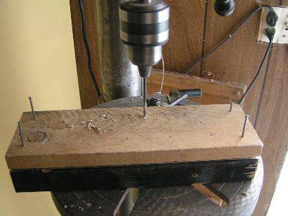
I used a piece of 2X4 for the fixture body, a piece of 1X4 for the base, and
pieces of 2X4 for the legs. I just took some pieces out of my scrap box.
The piece for the body was already painted. Also in the picture is
the piece of flashing I cut from a roll and the adjustable wood bit.
The adjustable wood bit can only be used on a drill press and can rip large
chunks of flesh off your body if you try to use it with a hand drill.
If you don't have an adjustable wood bit, you can use a flat speedbore wood bit
that is larger than the OD of your body tube. You will have to
wrap tape around your mold tubes so they fit good in the fixture base so
the core rod hole is aligned in the center of the grain. |
| |
|
| The first thing is to make sure that you can align all
the pieces, take them apart, and put them together again in the same
place because you are going to drill the holes in the pieces separately.
To do this, I drilled holes in the four corners of all three pieces, the
body, base, and wiper plate. I then put nails that just fit
snuggly into the drilled holes. I also made a paper template of
what I wanted the hole configuration to be. In this case, two rows
of four holes. This was laid out to get the most room between the
holes. It is then just used to center punch the fixture pieces. |
 |
| |
|
 |
 |
|
Here the holes are being
center punched. Notice that the base is the side being punched.
My paper template was a little short on one end but I made sure the set
of holes were centered on my fixture and that the holes would not
interfere with where I was going to mount the legs when I am done. |
Next pilot holes are drilled
where the board was center punched. I used a 1/8" bit for these
and used a drill press to make sure the holes were straight and
perpendicular to the base. |
| |
|
 |
 |
|
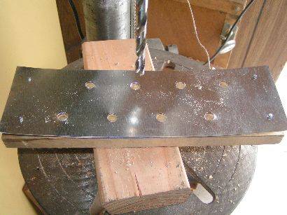
The body is removed and
holes are drilled through the wiper plate and the base. This
fixture will be used to make BATES grains for 1" PVC motor cases which
will have 3/8" diameter cores. This grain will work for motors
with one to four grains. When these holes are drilled, the wiper
plate is removed and the holes in the base enlarged to 1/2" or 5/8"
diameter. You have to use a twist drill to enlarge the holes.
Alternatively, you could drill the wiper plate and base separately and
use a flat speed bore bit on the base and a twist drill on the wiper
plate but the alignment may not be quite as good. |
Here the body holes are
being drilled. To use an adjustable bit, you have to drill several
test holes in scrape wood and check the diameter with a piece of PVC
pipe -- 1" in this case. Be sure to tighten the screw on the bit
very tight and check the diameter often because it will tend to get
bigger. The pilot holes drilled in the first step guide the
adjustable bit. When the adjustable bit breaks through the bottom,
it doesn't do that with finesse. It kind of makes a mess. It
isn't being done here but it would be much better to clamp the body
piece to another piece of wood while drilling so that the splintering
isn't so severe when it breaks through. |
 |
 |
|
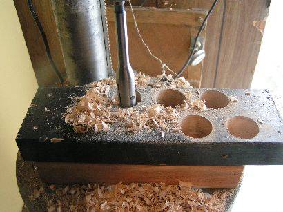
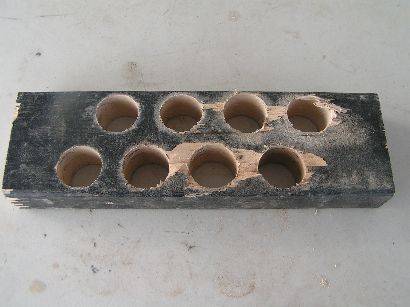
Here is the top side after the holes are bored. |
This is the bottom side of the fixture body. You
can see that there is a lot of chunks of wood ripped off the surface
where the bit broke through. |
 |
 |
|
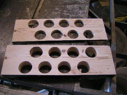
I decided to compensate for
the splintering by sawing a slice off the bottom. My 10" table saw
would not saw all the way through the 3-1/2" width of the board so I had
to saw part way through and then turn it over and finish it. The
surface was then sanded to even up the surface. This step isn't
really necessary because you will use pieces of PVC pipe in these holes
and the pipe will fit against the wiper plate so the splintered areas
don't effect the casting of the grain at all. The ID of the PVC
pipe pieces and the wiper plate are the surfaces that form the grain. |
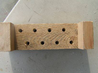
Here is the finished product with all the pieces screwed together with
screws through the original alignment holes. Notice that the legs
are on the outside of the outermost body holes. Now you should paint the fixture except for the holes so that spilled propellant
won't stick to the fixture and so you can show off your fixture and show
everyone what a quality carpenter you are. (Unlike me). |
|
|
|
 |
 |
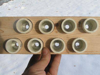
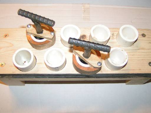
| This is a top view of the fixture body with the PVC
grain molds in place and showing how the core rod clearance holes are
centered in the grain molds. |
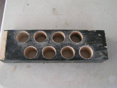
This shows the propellant plug clearance
holes in the base. It would have been better to have 5/8" holes
here but since I had drilled the 3/8" holes through the base and wiper
plate at the same time, I couldn't use a 5/8" speed bore bit and I
didn't have a 5/8" twist drill -- only a 1/2" twist drill. |
 |
 |
|
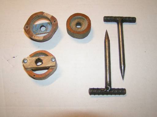
The last parts to make are the cap which is optional and the coring
tool, not optional. The purpose of the cap is to center the coring
tool as you push it through the grain. It also helps form the surface of
that end of the grain. Like the other side, you need aluminum foil
as a liner inside the cap. The first caps I made were what is
shown in the middle for a 3/4" grain. I didn't like how these
worked because when I pushed the coring tool down through the
propellant, it pushed the cap up off the top of the grain mold unless I
didn't fill the mold all the way full. It is difficult to gage how
much extra room to leave. so when I made my caps for the 1" mold,
I put a bar across for the coring rod hole so the excess propellant
could extrude out along the sides. Then I just took a sharp knife
and cut off the excess. That worked a lot better. I drilled
the large hole in a larger piece of wood first, then drilled the coring
rod hole, then cut out the cap from the larger wood, and finally sanded
it round (sort of). |
The coring rod I use is steel. I had some scrap rebar that I used for
the T-handles but the body here is 3/8" steel rod. I welded my
handles on but I have seen where other people have made wooden handles.
You need to be able to have some good leverage to twist and pull them
out of the propellant grain and that is why I chose the T-handle
configuration and welded them. You could also use a straight rod
and a pair of vice grips on it if you wanted to. Notice the long
taper to a sharp point. I experimented with different
configurations--round tip, short taper and finally the long taper.
The long taper to a sharp point was definitely the best. You don't
need a whole bunch of coring tools and caps for the smaller grains, at
least 1" or smaller and maybe bigger. They cool fast and you want
to pull them out before they set up very much so generally, two or three
are enough regardless of the number of molds in your fixture. |
Home ||
High Power Rocketry ||
Experimental Rocketry
|
|