|
Home ||
High Power Rocketry ||
Experimental Rocketry
Casings are just pieces of PVC pipe cut to length. You can calculate
your own lengths or use the lengths in the
design tables. To prepare the casing, you first have to decide on
the method of retaining the nozzle and header. There are a number of
methods that are explained on the
Casings, Nozzles & Headers page. You need to read that page in
detail before continuing here.
I
make up a bunch of casings at one time. If I am going to use ID
retainer rings, I cut a bunch of those at the same time as the casings and
scrape of the burrs on all the edges with a knife or sand paper. If
you have glued PVC pipe and fittings together before, then you know how easy
it is. You just use the cloth ball on the wire attached to the lid of
the cement can and run a circle of cement on the ID of the fitting, and the
OD of the pipe and shove them together. However, you aren't putting
together an outside sprinkler system with 40psi pressure, you are putting
together a precision motor to withstand 300psi or more. Not only that,
any dried drippings on the inside of the motor will burn and create a path
for gases to escape. First clean the parts to be glued together with a
clean rag. Next apply cleaner/primer to both surfaces to be mated
being careful to not be sloppy. You can allow dripping out the end
onto your newspapers but not to run down the inside of the tube so always
apply both the cleaner/primer and the cement with the end being coated
facing down and the rest of the casing up. Allow the cleaner/primer to
dry, then do the same with the cement. Quickly put the parts together.
Clean off any excess from the inside of the casing after putting the pieces
together. You can only put the nozzle end together for now because
obviously, you have to put the fuel grains in before you can add the other
end (header).
When putting in ID rings, it is a little trickier. You have to squeeze
it together first and hold it together while inserting it into the casing
while both have wet cement on them. First, sand or scrap a slight
bevel around the edge of the end of the ID retainer ring that you are going
to push into the case. You can also bevel the end of the casing a
little. If you have trouble holding it together, try using a pair of
pliers to squeeze the ring together while inserting it. make sure to
line up the end of the ring with the end of the case immediately because in
only a few seconds, it will be frozen in whatever position it is in.
There should be hardly any opening showing in the split ring after it is
inserted. The split should be together with the two ends touching.
If they aren't you probably have too big a split and you need to find a way
to make a narrow cut. A hack saw will make a very narrow cut and then
it can be sanded to open it up a little. Once you have found the right
split width, you should make a gage to check all future rings. You can
take something like a popsicle stick and sand it until it just exactly fits
or you could use feeler gages and find the right number of gages stacked
together to indicate the right gap. Write it down.
This is my second favorite way to retain the nozzles and headers. It
takes a little more work in my estimation but still pretty quick and easy.
I first decide on the number of holes around the tube and the size.
Here are the sizes I use.
|
PVC Pipe Size |
Hole Size |
|
1/2" |
11/64 |
|
3/4" |
13/64 |
|
1" |
17/64 |
|
1-1/4" |
21/64 |
|
1-1/2" |
3/8 |
|
2" |
15/32 |
|
3" |
11/16 |
I
use eight holes around the circumference equally spaced and approximately one
hole diameter from each end of the casing. . Then divide that distance into eight
equal sections.
I
use a drill press and a V-lock. My V-lock is just a piece of 2X4
(my favorite working material) that I cut a V in on my table saw with my
blade set at 45 degrees. I clamp it down to my drill press table and
but a small bit such as a 1/8" bit in the chuck. Without the drill
press running, I move the drill bit down to the bottom of the V, moving
the 2X4 so the drill bit tip hits exactly in the bottom of the V towards one
end of the block. That way, I can slide my casing into the V and drill
the hole exactly vertical and it won't tend to turn the casing or drill the
whole at an angle.
|
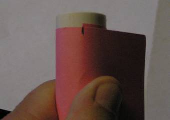
Take
a piece of card stock and wrap around the casing fairly tightly and mark
where one edge is so that you have exactly one circumference marked |
Unwrap the card
and lay it flat. |
|
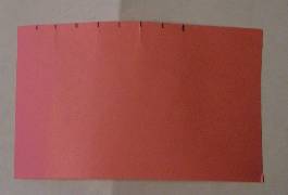
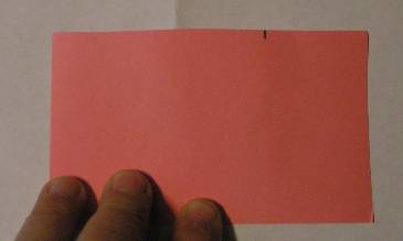
Measure
the distance between the side and the mark. Divide the measurement
by 8 and mark off eight even marks along the top of the card. |
Wrap the paper
back around the motor case and tape it. |
|
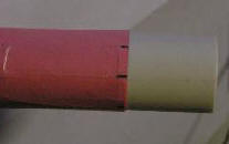
Measure 1.5 hole
diameters from the end and position your marked end of your card
template at that point. Draw a circle around the motor tube at
that 1.5 hole dia. position. Then mark the points adjacent to the
marks on the card stock tube. |
Now turn the card stock
template around and put it on the other end of the motor case and mark
that end the same. Now you need to indent the points at the
intersection of the circle around the case and the eight marks. I
put a small collet in my Dremel and a 1/16" bit and actually drill holes
at each point. You could use an ice pick or scribe or a center
punch and make a dent at the locations. |
|
After you have all the positions marked and have a hole
or dent at each point, put the motor tube in your V-block and drill all
the holes. Your motor case is now ready to form the nozzle. |
 You
can pour the nozzle in the motor case and then drill it afterwards but it is
very easy to damage it. I like to cast the throat into the nozzle.
It is a little more work but I don't damage them this way. To do this,
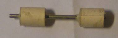
you need a nozzle mandrel. I use a wooden dowel with a hole drilled in
it and a metal rod (often just a drill bit) in the whole and sticking out
long enough to be longer than the nozzle. drilling the hole in the
center of the dowel is tricky and difficult to get exactly in the center and
straight. This one was actually made before the method below and it is
a little crooked. That is why I came up with the following way using a
centering tool. You
can pour the nozzle in the motor case and then drill it afterwards but it is
very easy to damage it. I like to cast the throat into the nozzle.
It is a little more work but I don't damage them this way. To do this,
you need a nozzle mandrel. I use a wooden dowel with a hole drilled in
it and a metal rod (often just a drill bit) in the whole and sticking out
long enough to be longer than the nozzle. drilling the hole in the
center of the dowel is tricky and difficult to get exactly in the center and
straight. This one was actually made before the method below and it is
a little crooked. That is why I came up with the following way using a
centering tool.
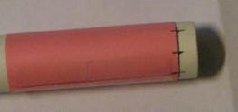
 This
is a centering tool. It is a piece of brass tubing that I got at a
local hobby shop. Any hobby shop should have a rack of tubes for hobby
use. This tube has an internal diameter such that a 1/8" drill bit
just slides into it. This pieces is 4" long. I wrapped paper
around it in two places as shown. The first wrap was taped to the tube
itself so the paper wouldn't turn on the tube. I wrapped enough layers
until it would just slip into a piece of PVC the size of my motor cases
(this one is for a 3/4" motor case). This will center the tube exactly
in the center of the 3/4" PVC pipe. The motor tube or any piece of PVC
pipe the size of a motor tube can be used and is just used to hold the
nozzle mandrel. Next I bought a jobber length 1/8" drill bit that is
12" long. This
is a centering tool. It is a piece of brass tubing that I got at a
local hobby shop. Any hobby shop should have a rack of tubes for hobby
use. This tube has an internal diameter such that a 1/8" drill bit
just slides into it. This pieces is 4" long. I wrapped paper
around it in two places as shown. The first wrap was taped to the tube
itself so the paper wouldn't turn on the tube. I wrapped enough layers
until it would just slip into a piece of PVC the size of my motor cases
(this one is for a 3/4" motor case). This will center the tube exactly
in the center of the 3/4" PVC pipe. The motor tube or any piece of PVC
pipe the size of a motor tube can be used and is just used to hold the
nozzle mandrel. Next I bought a jobber length 1/8" drill bit that is
12" long.
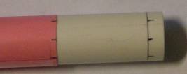
A
wooden dowel is cut so it will have a little sticking out the bottom of a
motor case when the nozzle end is at the upper end of the nozzle.
Again, PVC pipe is not a nice common dimension on either the inside diameter
or the outside diameter. To make the mandrel fit nicely in the PVC
pipe, I wrapped tape around both sides of the dowel until it just fit
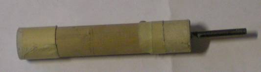
Now
the prepared dowel goes into one end of the piece of PVC pipe and the
centering tool goes in the other end. The PVC pipe should be cut to a
length so that the centering tool comes into contact with the end of the
dowel and both the dowel and the centering tool stick out far enough to hold
onto. You need to hold both so they don't turn. Now you just
insert the jobber length 1/8" bit through the centering tool and drill a
hole in the center of the dowel. Even with the centering tool, the
grain of the dowel can pull your drill bit crooked as you drill deeper into
the dowel. You can minimize this by drilling very slowly letting the
drill bit have time to cut through the grain of the wood rather than trying
to follow the grain off at an angle. You can use a similar method for
larger motors and could use a 1/4" jobber bit and the rest of the pieces
sized accordingly. The 1/4" bit shouldn't wander as much.
Once you have the hole drilled into the dowel, you can enlarge it to any
size and the large drill bit will follow the 1/8" hole. The depth of
the hole should be determined before you start and you can wrap a piece of
tape around the jobber length drill bit as a drill stop so you drill to the
depth you want. The hole should be to a depth that if you are going to
use a drill bit for the nozzle throat core, the drill bit when it bottoms
out in the hole has enough protruding that it will extend beyond the end of
the nozzle.
Forming the Nozzle
 |
 You set the motor
case up as shown at left with the Nozzle mandrel in the motor case.
The nozzle must be at least the same length as the inside diameter of the
case. 1-1/4" times the diameter is better. Put a mark on the
bottom of the mandrel at the bottom of the case. You set the motor
case up as shown at left with the Nozzle mandrel in the motor case.
The nozzle must be at least the same length as the inside diameter of the
case. 1-1/4" times the diameter is better. Put a mark on the
bottom of the mandrel at the bottom of the case.
When you pour in the Rockite or other quick set cement, it will want to come
out the circumferential holes. I wrap a piece of plastic around the
tube to cover the holes. I used a piece cut from a clear plastic cup
but you could also use the plastic from an overhead projector view foil.
I have used paper and tape, too, but I like to see the holes to make sure
the cement is coming out a little so I know the holes are filling with
concrete.
You
need to set the motor case with the mandrel into something to hold it
upright. You could just cut a hole in the top of a cardboard box just
enough to wedge the case into it or you could get fancier and make something
out of wood.
Mix
up the Rockite until it is like thick pancake batter and then pour/scoop it
into the top of the motor case. Work it down to the bottom and use a
small dowel or stick to make sure all the bubbles are out. If you are
using washers to prevent the throat from eroding, push them down over the
throat rod and about half way down into the cement. I use another
brass rod that just slips over the throat rod with a piece of tape around it
to gage the depth I am pushing the washers to.
|
It
will take about 15 minutes for the Rockite to start setting up. When
it just has set up but while still uncured and wet looking, carefully pull
the nozzle mandrel out. If you wait too long, the throat rod will come
out with difficulty and you may have to use a pair of pliers and pull it out
the top. This could damage the nozzle. Keep an eye on the cement
and pull the mandrel out at the right time.
Once the mandrel is removed, wait just a few more minutes to let the nozzle
set up more fully. Then form the exit cone and if you want to, the
entrance cone. Again, if you wait too long, it will be more difficult
to form the cone.
 I
used a speed bore wood bit ground down to form the exit (divergent) cone.
The tip is at the almost exact right angle, 30°.
I
used a speed bore wood bit ground down to form the exit (divergent) cone.
The tip is at the almost exact right angle, 30°.
I
use a countersink on an extension shaft to form the convergent nozzle.
You
will need different mandrels for each motor size even if you use the same
case because the throat diameter will be different. What I have done
to cut down the number of mandrels is to make the hole in the dowel the size
of the largest throat diameter and then for smaller diameters, I wrap tape
around the rod or drill bit so it fits snuggly and is centered. One
disadvantage of this is that if you have to use pliers to pull the rod out
of the nozzle because you waited too long, you won't be able to do it
because the tape won't come through the nozzle throat. You will have
to break out the nozzle and destroy your case to get it out.
Sealing the
Nozzle
One
last thing is that for higher pressure or if you are having exhaust leaks,
you will need to spread a bead of RTV, the tube of red silicone high
temperature gasket goop that you can get at any auto parts store, around the
inside of the case where it meets the nozzle to help seal it and form a
gasket. This is somewhat equivalent to the o-rings used on commercial
reusable rocket motors. This is done with a long stick and is not very
easy to do, especially with longer cases. You have to be careful that
you don't get it smeared on the inside wall. If you do, you need to
remove it because you won't be able to get your propellant grains down past
the smears. Let it set up before you load your propellant grains.
Loading Propellant Into the Motor Casing
After you have formed your nozzle with the cones, you can either put away
the case until later or immediately load the fuel grains in and form the
header.
When you load your propellant, just push the grains down into the case until
it bottoms out against the nozzle or the ring of RTV. Then you need to
seal the top with a paper disk or a piece of aluminum foil pushed down
against the top of the grains. This will keep the wet cement from
softening the fuel grain and keep the concrete out of the core of the
grains. I just cut some squares larger than the OD of the case and use
a dowel to push the foil down against the grains. Then I smash the
corner of the squares down to form a disk of tin foil.
Header
Another small batch of cement is prepared and added to this end in the same
way as when forming the nozzle except without the mandrel.
Time Delay
If
you are going to use a motor time delay, then you will need to make the case
longer, add another grain of propellant without a core and the right length
for the delay. The delay charge should have a coating of RTV on the
outside to prevent gases from going around it and forcing it to burn from
one end to the other end. There should be additional room above the
header, also. A small hole, 1/16", is drilled carefully through the
header and just into the delay grain. Make sure the hole is clean with
no particles from the drilling in the hole. 4F smokeless powder is
shaken down the hole and the ejection charge placed in the motor case above
the header. a cardboard or fiber disk is then pushed into the last
upper part of the case above the ejection charge. This disk must be
tight but not glued in. See the free
manual for details. The details are the same as for black powder
motors.
The
concrete will set up quickly but gets stronger the longer it cures.
Ideally, wait at least a day or two before firing the motor. I have
fired them within a couple hours but have a lot more leaks and failures than
when I let them sit a couple days first.
You
should test a few motors first before flying them in rockets to make sure
you have a consistent method for all steps and can trust the motors to work
properly. Even commercial motors sometimes CATO. Homemade ones
are usually less reliable unless you have been making them a while.
Consistency of process is the key. Write down everything you do and
when they work, do it exactly the same.
Storage
Normally, you would make your grains, put them in a desiccator box for a
couple days or more first and then either keep them in the desiccator box
until you are ready to load them or you would seal them in zip lock bags or
by wrapping them in aluminum duct tape to keep out the moisture. You
might also then put the desiccator box or the otherwise sealed grains in the
freezer. Then you would take them out just a couple days before you
are ready to load your motors, load your motors, wait a couple days and then
fire them. However, you can also make up your motors ahead of time and
store them the same way you would store your grains. It is actually a
lot easier to keep the moisture out of a loaded motor because only the
nozzle orifice exposes the grain to the atmosphere. I keep everything
in a desiccator to make sure they stay dry but you could also seal the end
of the nozzle other ways such as with aluminum duct tape, a rubber plug, or
anything that will insure the nozzle is sealed.
Home ||
High Power Rocketry ||
Experimental Rocketry
|