
Constructing the mold is probably the most difficult aspect of fabricating the rocket engine. It must be made relatively accurately to function properly and to accomplish this requires at least an accurate drill press and a metal lathe would be an enormous asset.
The mold accomplishes three things. It holds the engine casing securely in an upright position. The piercer forms the core in the engine which is necessary to give the engine sufficient thrust. The mold body contains the case against the large pressures applied to the case during loading and prevents it from bursting.
In addition to the mold, loading dowels must be constructed. These are merely dowels the same diameter as the rolling mandrel. They have holes drilled in them progressively smaller to be used successively in loading the engine. The smaller holes accept the smaller tapered portions of the piercer. Drilling the long straight holes accurately in the loading dowels and mold body is the task that presents the most difficulty.
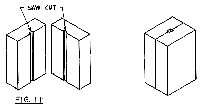
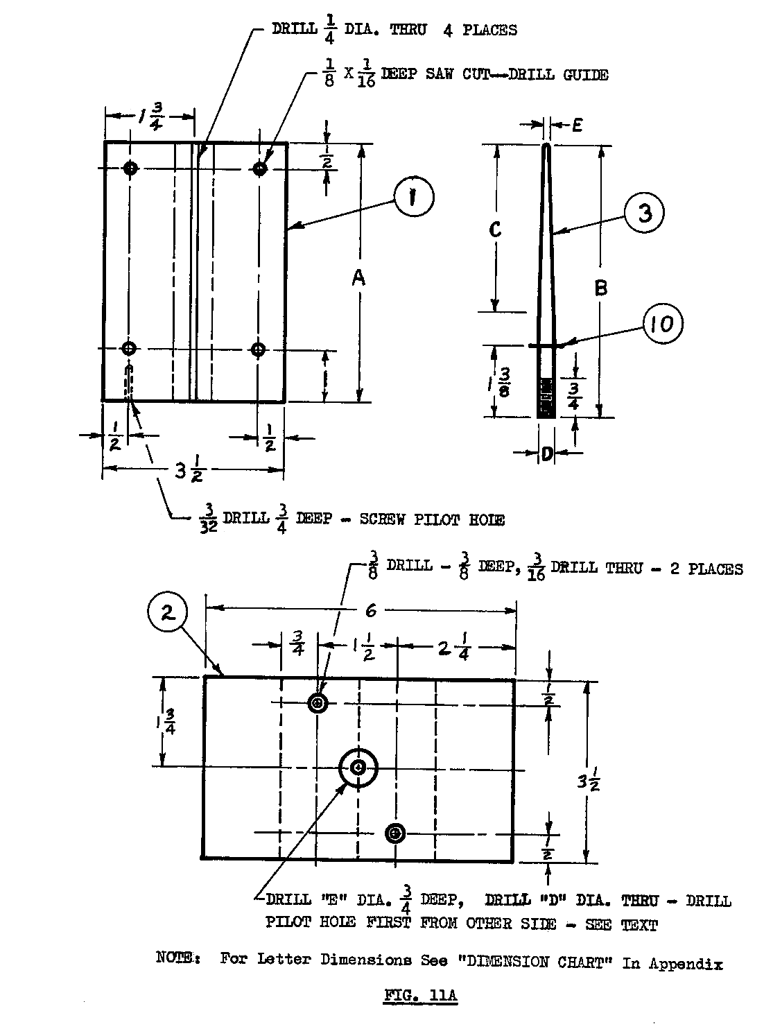
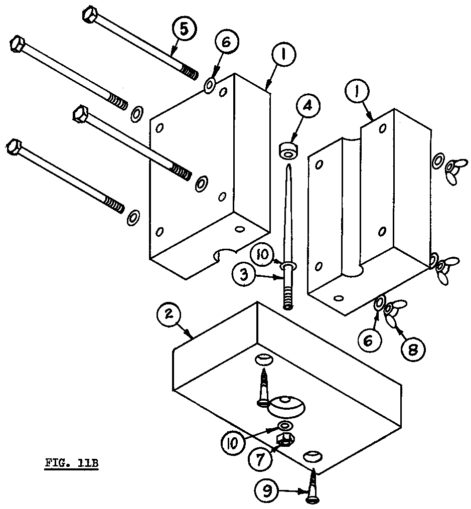
Refer to Figure 11, 11a and 11b for the construction of the mold. The case is made from three pieces of standard 2x4 board. The base is six inches long. Refer to the dimensions chart (Appendix I ) for the length of the body. Figure 11a gives all the hole placement specifications and other needed dimensions.
Cut the two body halves about two inches longer than the finished length allowing an inch on each side.
Cut a groove 1/16 inch deep and the width of the blade (1/8 inch) in the exact center of the mold halves. (see Figure 12) Line up these grooves on each end so that they form a square hole through the mold body when together. Temporarily nail the two halves together with the slots lined up. Trim both ends to the final length. Take great care to make these cuts absolutely perpendicular to the sides. If these cuts are not square it will be very difficult to drill the casing hole straight.
Figure 11

Drill the four quarter inch holes on the sides through both halves. Use four quarter inch by four inch long bolts to fasten the two halves together. Use flat washers on both sides or use carriage bolts and washers just beneath the wing nuts.
Bolt together the two halves of the body and tighten the wing nuts. Counter bore the two screw holes on the base and drill the pilot holes through. Center the base on the body with the counter bored holes away from the body and extend the pilot holes into the body. Now enlarge the pilot holes in the base to the screw clearance hole size and screw the base to the body.
Drill the casing hole using either wood boring bits or an expansive auger bit with a self starting screw point. The tapered square shank end can be cut off so it can be used in a drill press. Take the mold apart a couple times and check to make sure the bit is still drilling straight. The drill should be stopped after the tip has entered the base but before the cutting blade cuts into the base. The last little piece of the body at the bottom of the hole can be cleaned out with a sharp knife.
For the taller molds, the expansive bit will not be able to reach the bottom. A machine shop can extend the shank for you or the remainder of the hole can be drilled with a wood boring bit and extension by hand, or by a longer auger bit and brace. It is easier to keep the bit straight after the main hole is drilled. Just keep the shank in the center of the top of the hole.
Remove the base from the body and drill an eighth inch or smaller pilot hole through the base where the auger bit tip drilled into it. Turn over the base and counter bore the piercer hole, then drill the piercer diameter hole through.
The piercer is most easily formed on a metal lathe. It should be made from steel ideally though experimental or temporary piercers can be made from wood and glued in place. The wood piercer can be easily formed by hand on a disk or belt sander but cannot be made very uniform. It can also be chucked in a drill press and then shaped using rasps and/or sanding blocks. The problem with wood piercers is that they break very easily, especially the smaller ones. Even with a coating of soap, a twisting motion will snap them off. The engine must be pulled straight off the spindle and if not securely glued into the base can be pulled out. Wood is porous and also compresses when the propellant is compacted. These factors make them adhere very tightly to the engine core. A considerable pressure is used to compress the propellant into the casing and it is sometimes necessary to stand on the base after removing the body and pull with considerable strength to separate the engine.

Metal piercers, however, generally are quite readily removed from the engine. The piercer could also be made from brass or aluminum. The piercer can be made from plain rod or from a long bolt with the head removed. The tapered section is turned on the unthreaded portion of the bolt. If plain rod is used, threads are cut on the opposite end or formed with a die. Normally, the small end of the taper is half the diameter of the large end but many specialized shapes can be tested to obtain different burn characteristics.
If a lathe is not available, the tapered piercer can be shaped by chucking it in a drill press and using a hand held power grinder or flat files. The files are very time consuming, though.
A washer is brazed onto the piercer just above the threads. It is imperative that the washer be exactly perpendicular to the threaded portion so the piercer will extend up through the exact center of the casing hole. The brazing should be done on the threaded side. A hole the diameter of the piercer can be drilled in a scrap of 2x4 and the piercer pushed through it upside down to hold it perpendicular. The washer can then rest on top of the board. Use additional washers under it for a heat sink. Rather than braze the washer on, the piercer can be threaded far enough to put a nut on the top of the base also. The nut must be counter sunk into the base so the top is even with the top of the base. Bolt the piercer in place using a flat washer and nut in the counter bored hole. Check to make sure when the mold is completely assembled that the top of the piercer is in the exact center of the bore in the body.
Other methods of attaching the piercer to the base can be used as long as it is positively secured and is aligned absolutely vertical and in the center of the casing hole in the mold body.
The nozzle spacer is made from a dowel the same diameter as the mandrel. Drill a hole the same diameter as the base of the piercer exactly centered in the dowel. Cut it off half as long as it's diameter. For the smallest molds, the spacer may have to be metal. Slide the spacer onto the piercer and the mold is complete.
The loading dowels are most easily made in a metal lathe. They can be placed in a three jaw chuck with some thin cardboard around them for protection and then drilled. This is really the only way to accurately center drill the holes.
Four loading dowels are made for each size engine. The first has a hole drilled the diameter of the base of the piercer and as long. The second dowel should be long enough to accept two thirds the length of the piercer and have a hole diameter just large enough to accept the diameter of the piercer at that point. The third should accept only the top third of the piercer with a proportionately reduced hole diameter. The last dowel has no hole and is used to compress the last charges.
If no lathe is available, a length of 4x4 can be sawed square and have a hole drilled perpendicular to the bottom the size of the loading dowel. A base can then be attached to it, the dowel inserted in the hole, a nail used to secure the dowel, the dowel centered under the drill bit and the base clamped to the drill press table. If the base is not clamped the drill bit will invariably wander. If the drill bit is sharpened unevenly or if the grain in the dowel runs diagonally, the drill bit may wander anyway.
If the hole in the dowel is drilled crooked so the drill bit comes close to the outer surface of the dowel or comes out of it, the dowel will collapse in use and be ruined. If the hole is started off center it can force the piercer off center and cause the engine to malfunction.

1. 2 X 4 wood "A" inches long -- 2 req'd
2. 2 X 4 wood 6" long
3. Piercer -- "D" inch dia. rod -- "B" inches long
4. Wood dowel -- same dia. as case I.D., half that dia. long
5. ¼" hex head or carriage bold 3½" long -- 4 req'd. *
6. ¼" flat washers -- 4 req'd *
7. "D" inch nut
8. ¼" wing nuts -- 4 req'd.
9. #10 wood screw 1-3/4" long -- 2 req'd.
10. "D" inch flat washer -- 2 req'd.
*Note: 1/4" and 3/8" molds require only two bolts (item 5) centered vertically on mold body. 7/8" & 1" require 6 bolts, the extra 2 centered between the bolts shown.
| ◄ first page | ◄ previous page | next page ► | last page ► |