|
Back to Rocket Manual
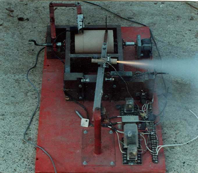
This is the
same picture used in the brochure.
What it does
This machine, though
looking crude, actually does a lot and does it accurately. Here is
what it does:
-
Ignites the engine remotely
-
Draws a thrust-time curve
-
Records the time delay for the ejection
charge
-
Works with all sizes of engines
How it works
The engine is mounted
on a rigid arm that pivots around an axis on one end. A calibrated
spring is attached to the arm. When the engine fires-it moves the arm
a distance proportional to the thrust developed. At the end of the arm
is a weighted ink pen that writes on a strip of paper wrapped around a drum.
The drum rotates at a specific speed so the thrust is recorded as the drum
moves and the result is a thrust time curve. The arm is long compared
to the arc it moves in so the error due to moving in an arc rather than a
straight line is minimal. The mass of the arm is also very low
compared to the engine force so that error is also minimal. The motor
that drives the recording drum is automatically started at the same time as
the electrical ignition for the engine.
In addition, another pen scribes a line below
the thrust time curve. This pen is driven off a screw on the same axle
as the drum and so moves a small amount across the drum as the drum rotates.
This way, it doesn't overlap itself as the drum makes multiple revolutions.
This is so that a delay can be recorded that lasts more than one revolution.
A small photo sensor is mounted on the forward end of the engine and detects
the flash of the ejection charge. This triggers a solenoid that causes
this second pen to move and so records the time of the ejection charge
relative to the main thrust time curve. The crank is so that the coupling
to the drum can be loosened and the screw can be backed up easily to the
starting point for the next test.
Different size engines can be tested from the
tiniest 0.25" ID to the largest 1.25" ID. A number of different
springs were used and each one was calibrated. The stationary end of
the spring was attached to an eye bolt which could be easily and quickly
changed for different lengths of springs so all charts were made from zero
force.
Construction.
The construction can be seen fairly well from
the picture. All components were easily obtainable and were made with
nothing more than standard hand tools, a table saw, drill press, and a gas
welder (used to braze a few parts). The drum was a piece of PVC pipe,
probably about 3" sched. 40. Wooden circles were cut and sanded to fit
the two ends and a 1/8" steel shaft was run through it. An old
ErectorSet part was used to fix the shaft to the wooden end. The drum
motor I think was ordered from Graingers. It was a 115V AC gear-reduced
motor that only turned about 1.5 RPM. I was thinking it was a BBQ
rotisserie motor but from looking at the picture, apparently not.
The photo sensor, relays, amplifier for the
photo sensor and transformer (115V to 12V for igniter) were ordered from
Graingers. The solenoid was out of a 12V solenoid operated water valve.
The arm was aluminum angle and on the end was attached a piece of hack saw
blade. This acted as a spring and supplied the pressure to make the
ink pen write. All the other pieces were just wood, steel plate, steel
rounds, and steel flats.
Hundreds of engines were tested on this
machine. Unfortunately, I didn't keep any of the charts but a few were
reproduced for the manual and brochure.
Back to Rocket Manual
|